Efficient and well-founded materials research requires powerful methods of materials characterization and testing. Fraunhofer IWS uses modern equipment in metallography, electron microscopy and mechanical materials testing. Thus, a targeted correlation between the material structure and associated fatigue properties of materials and components can be established or the influences of manufacturing parameters on the mechanical properties can be determined.
Laboratory equipment
- Cutting and embedding machines
- Modular grinding and polishing machines; vibratory polisher, electrolytic polisher
- Chemistry and etching laboratory
- Preparation robots for fully automatic production of serial sections (serial sectioning)
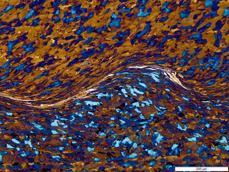
- Inverted reflected-light microscopes for microstructural analysis
- Image archiving and analysis software
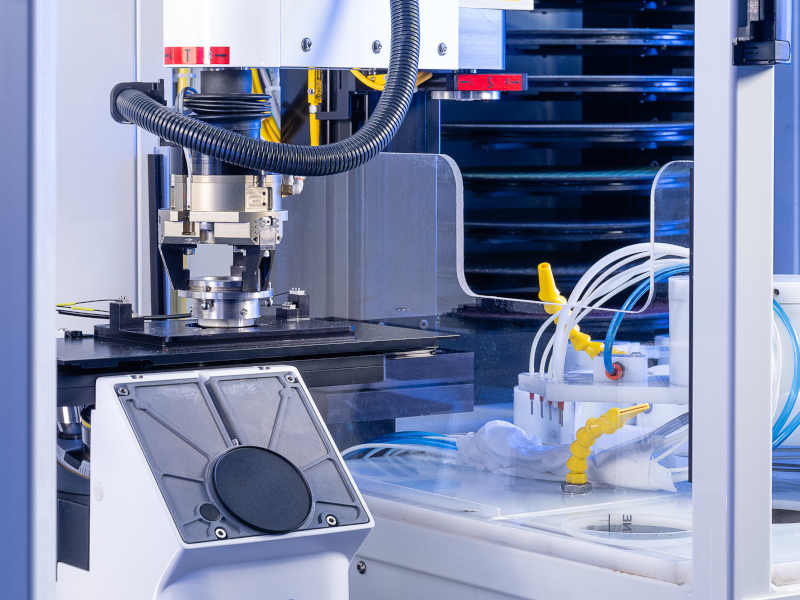
- Macrophotography and stereomicroscopy
- Fully and semi-automatic microhardness testing systems (Vickers, Knoop)
- Macro, small load and micro hardness testing machines including mobile equipment for on-site measurements
- Muffle furnace for heat treatment tests
Use
- Preparation of specimens for light and electron microscopy
- Light microscopic microstructure analysis of metals, ceramics, plastics and material composites
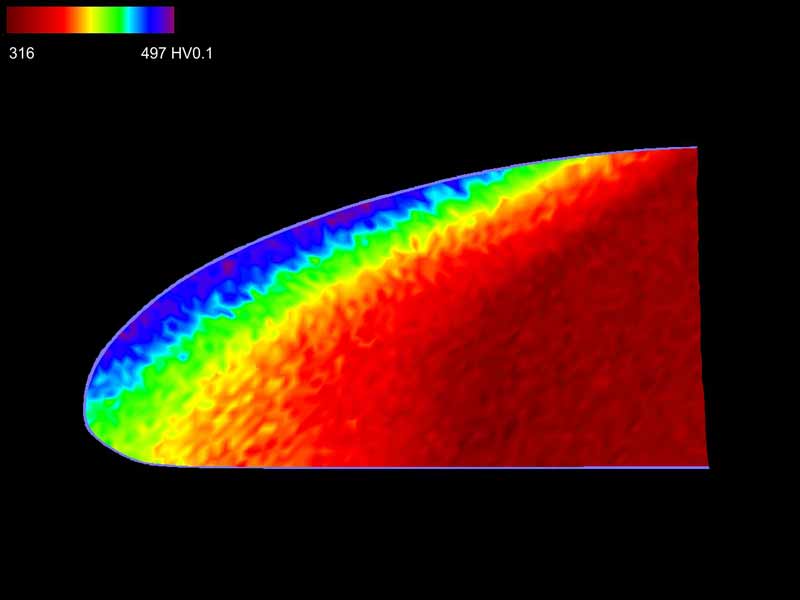
- Microhardness measurements: Hardness curves, hardness measurements along isolines, hardness mapping
- Hardness measurements: Small load hardness according to Vickers, macro hardness according to Vickers, Brinell and Rockwell
Electron Microscopy
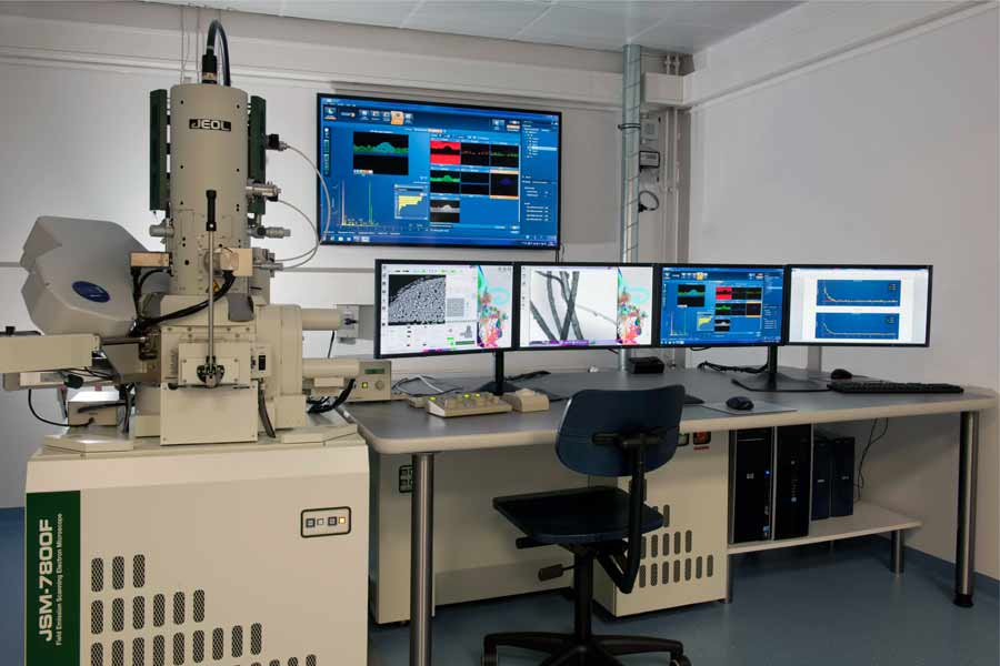
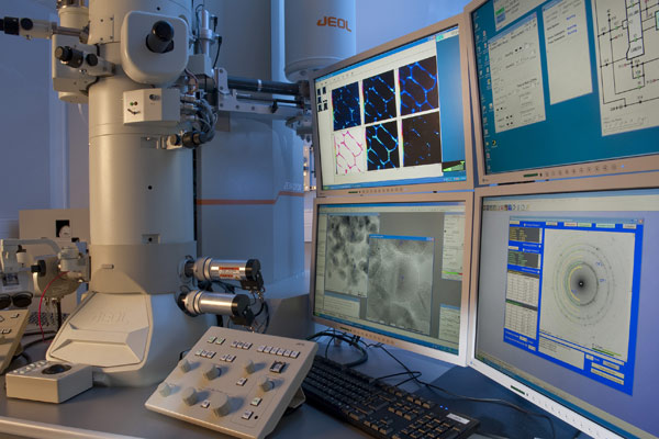
Analytical scanning electron microscopes
5 Scanning electron microscopes, 3 field emission instruments, 2 W cathode instruments with:
- Ultra-high resolution down to 0.7 nm, optimized for high beam currents
- Imaging with in-lens detectors, detectors for secondary electrons and backscattered electrons, STEM
- 4 EDX systems; 2 EBSD systems, optimized for high resolutions and high count rates
- Transfer system for sample handling under exclusion of air
- Possibility for low vacuum operation (Environmental SEM)
- In-situ deformation module
Application
- High resolution characterization of surface morphology
- Microscopic and nanoscale microstructural analysis (grains, phases, 2D and 3D lattice defects)
- High resolution analysis of thin films and modified edge layers
- Fractographic evaluations
- Chemical composition determination, including light elements (Be, B, C, N, O)
- 3D analysis of materials, tomography and 3D reconstructions; each combinable with EDX and EBSD analyses
Analytical transmission electron microscope
Analytical Transmission Electron Microscope
- 200 kV accelerating voltage
- 4-stage condenser system for flexible beam control
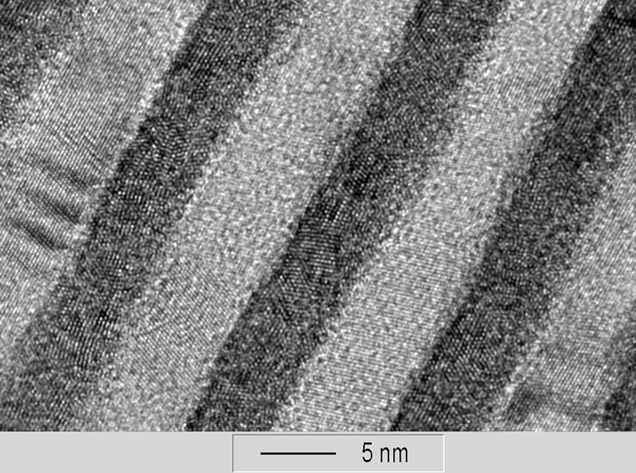
- High-resolution analytical pole piece: resolution: 0.14 nm; sample tilt ± 30°
- Advanced multiscan camera systems:
- Wide-angle camera for fast live image, overviews and diffraction imaging
- High resolution camera with excellent image quality
- Scanning equipment (STEM)
- EDX analysis system
- Preparation technique (electrolytic polishing, electrolyte beam and ion beam preparation)
Application
- Conventional transmission electron microscopy
- High resolution transmission electron microscopy (HRTEM)
- Electron diffraction: Fine area diffraction (SAD) and nano diffraction (NBD).
- Scanning transmission electron microscopy (STEM): bright and dark field imaging (HF, DF, HAADF)
- Energy dispersive X-ray spectroscopy (EDX): point analysis, linescan, mapping, sequential analysis, drift correction
Ion beam unit
Ion Beam Unit
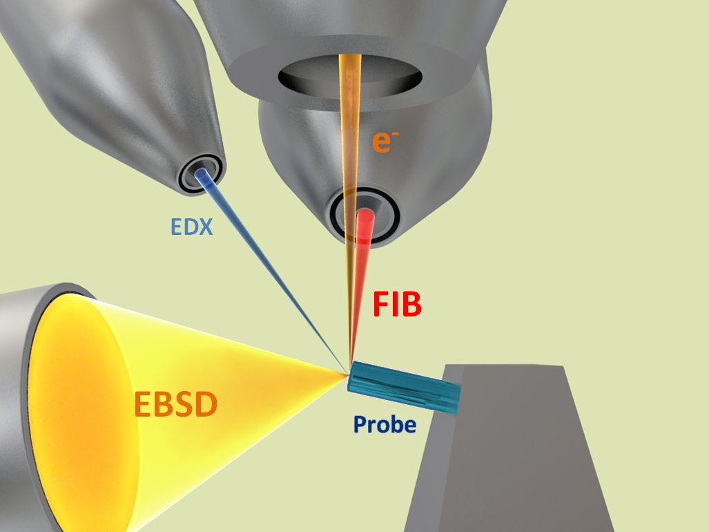
- Dual Beam System: Focused Ion Beam (FIB) and Electron Beam Imaging combined with EDX and EBSD Analytics
- Ion Beam Systems Cross Section Polisher
- Ion beam polishing systems “PIPS 691“ and “PIPS 695“
Application
- Microfabrication, nanofabrication: Production of various geometric structures; freely selectable patterns, 3D microcomponents, typical accuracy: 10nm
- Serial cutting (“slicing“, serial sectioning)
- High-precision, low-damage and effective TEM sample and target preparation of a wide variety of materials and layer systems
- Efficient processing of large areas and volumes by ion ablation with large ion currents
- Preparation of deformation-free and sharp-edged cross-section specimens for SEM and EDX analysis, including sample handling in the absence of air
- Preparation of heterogeneous materials, complicated layer systems, modified edge layers and joint interfaces
- Electrolytic polishing and etching of metallic materials
Mechanical Materials Testing
Materials testing laboratory
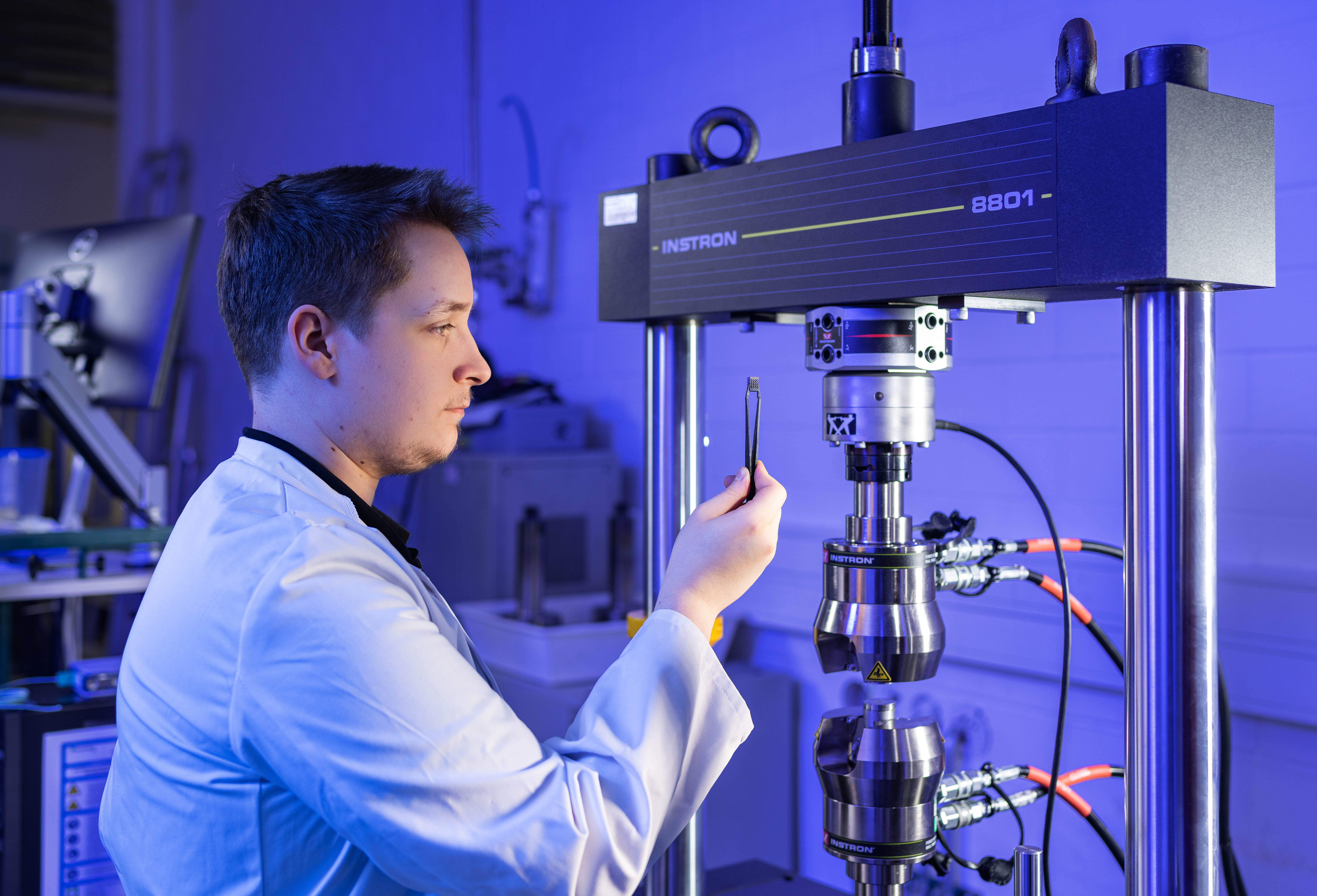
Determination of fatigue properties of additive manufactured lattice structures on a servo-hydraulic universal testing system.
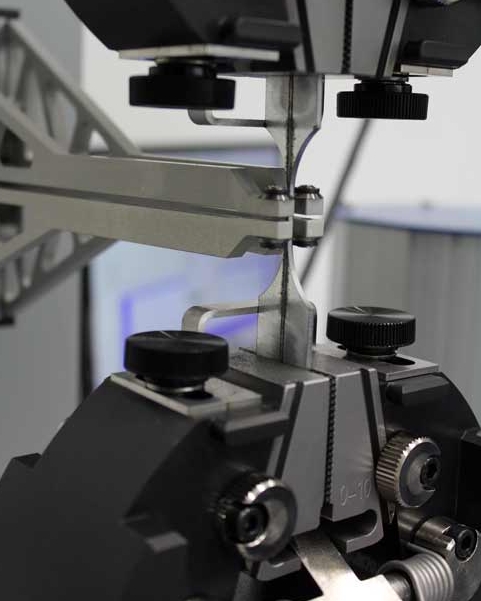
Test setup for the determination of weld metal properties as input for numerical simulation using a universal testing machine with fine displacement transducer.
- 3 servo-hydraulic testing machines (25 kN, 100 kN, 500 kN)
- Electromechanical universal testing machine (50 kN)
- Torsional axial testing machine (±8 kNm, ±50°; ±40 kN, ±50 mm)
- Circumferential bending test rig for determining the circumferential bending fatigue strength of material specimens and components (2000 nm, 600 to 3000 rpm)
- Tensile-compression module for in-situ loading (10 kN)
- Cavitation wear test rig
- Wear test rig for a tribological pairing (pin/bushing)
- Contact stylus device for measuring surface roughness and waviness
- Mobile measuring amplifier, e.g. for strain, force or temperature measurements
- Digital Image Correlation (DIC) system for area-based measurement of deformations and strains on components and specimens
- Camera systems for optical deformation analysis
- Notched bar impact pendulum (150 J, 300 J)
- Tensile, compression and flexure testing (-150 to 600 °C)
- Testing under torsion and/or combined torsion-axial loading
- Determination of surface strain by means of strain gauges
- Fatigue testing (Wöhler curves, cyclic stress-strain curves)
- Fracture mechanics (fracture toughness, crack resistance curves, fatigue crack propagation)
- Wear testing (cavitation)
- Roughness measurement, acoustic emission analysis, thermography
- Notched bar impact tests at different temperatures
Application
High-frequency test laboratory
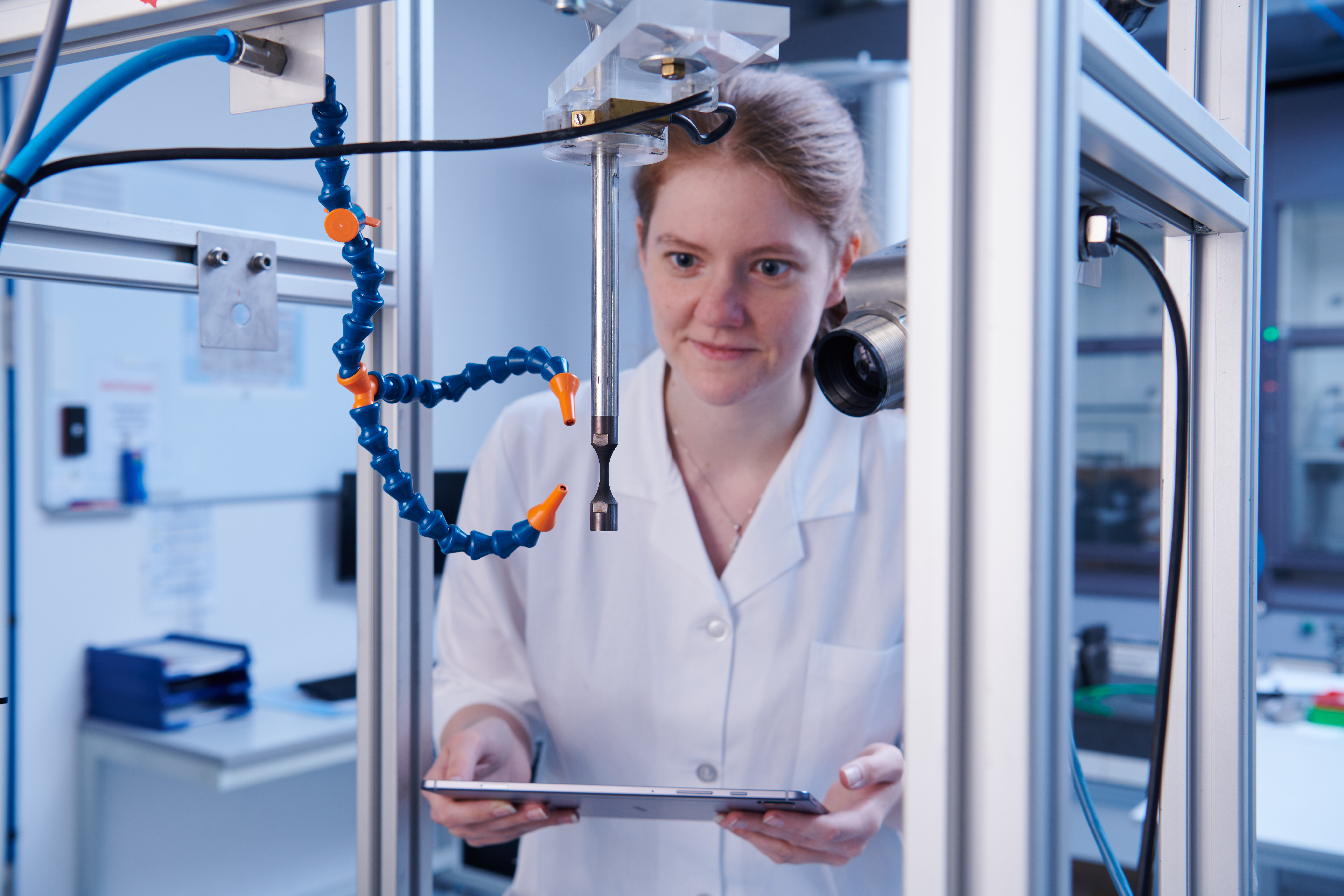
Ultrasonic fatigue testing system for rapid determination of the fatigue strength of materials.
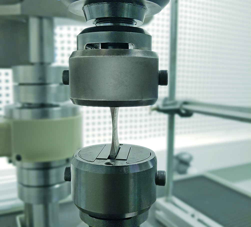
High-frequency resonance pulser with application-oriented, thin-walled specimen shape.
- 2 ultrasonic fatigue test benches (f ≈ 20 kHz)
- High-frequency fatigue up to 108–1010 oscillations
- Material-specific specimen geometries (round or flat specimens)
- 3 electromagnetic resonance pulsators ( Fmax=50 kN at f ≈ 1,000 Hz and Fmax=100 kN with 40 Hz ≤ f ≤ 250 Hz)
- Testing of material specimens and components
- Test conditions similar to those in use (temperature, oil bath, salt spray, etc.)
Application
- High-frequency fatigue of material specimens and components in the HCF and VHCF range (vibration cycle numbers up to 1010).
- Fatigue testing can be realized under near-use test conditions (temperature, oil bath, salt mist, etc.)
- Short-term diagnostics, highly accelerated relative comparisons of different conditions, manufacturing parameters, etc. using RF test technology
- Load in single-stage test or multi-stage test
- Load increase tests, stair-step tests, fatigue tests with holding times
- Testing in tension/compression, in tension threshold range or compression threshold range
- Fatigue crack growth, da/dN, fracture toughness tests
 Fraunhofer Institute for Material and Beam Technology IWS